Riyas P.K-Fab Academy 2016
Electronics Design
The assignment for this week is to redraw the echo hello-world board, add (at least) a button and LED (with current-limiting resistor), check the design rules, and make it. If possible, we could also simulate its operation.
Desigining the circuit in Eagle
First thing is to download and install Eagle.During installation there is option to use it as a freeware, which is more than enough for us.There are plenty of Eagle tutorial on web.I found these very helpful.
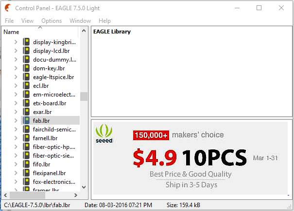
Then download fab.lbr(fab library components),and place it on the lbr folder of Eagle installation.Then open Eagle,and from its control panel find the fab.lbr listing.Right click it and select use.Now it is accessable during design.
Now create a new Schematic.Now add components from library.(components under fab)
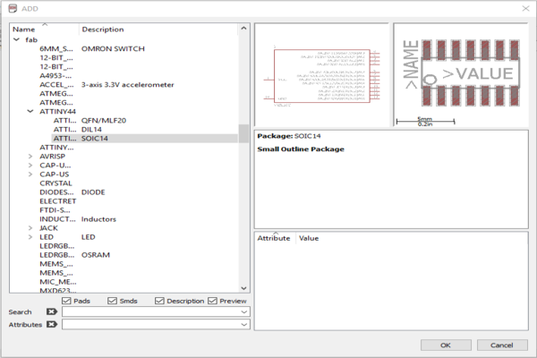
- ATtiny44-SSU
- AVR ISP SMD header
- 6mm Switch Omrom
- 20mhz resonator
- FTDI SMD header
- 10K resistor x 2
- 500 resistor
- 1µF capacitor
- LED
- GND
- VCC
After placing them use net tool craete connection.You can give name and value to components using respective tools.After finalizing check for errors using ERC error.I got two errors and some warnings.
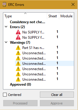
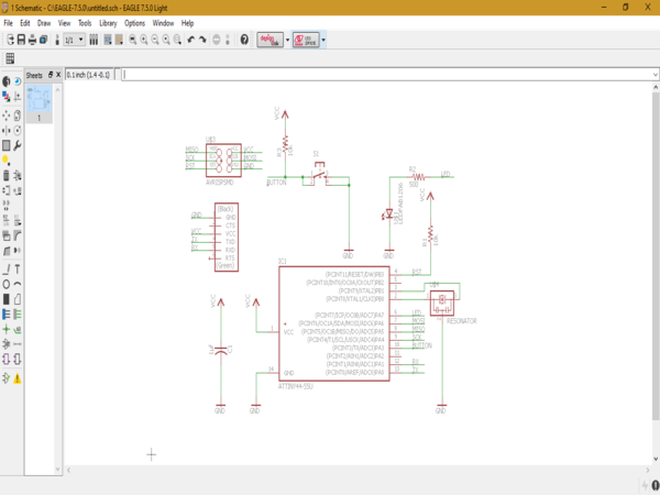
I corrected the errors and warnings and here is the final Schematic:
Board
After completing Schematic you can directly go to Board view.
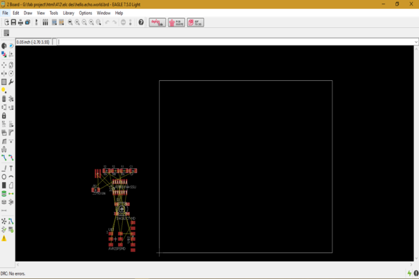
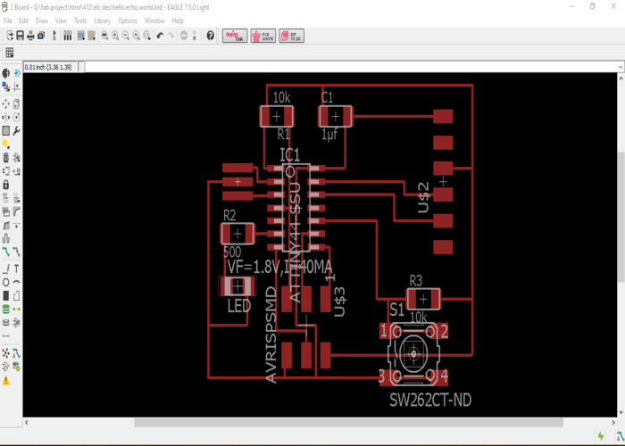
Everything was messed up.I first tried auto routing,but it made worse.So I decided to do it manually.Using the original echo.hello.world as a standard I began to place the components at specific parts.Then placed the LED and Switch appropriate places.Then using route tool I made paths.The default thickness made it overlap so, I changed its thickness.After so much messes I finally completed the board diagram.For a personal touch I added letter 'R' to the board.
Then for milling it needs to be exported as png.For this turn off all but layer 1 to export just the circuit traces.I then exported the circuit traces using monochrome, 500 dpi, window --- note the pixel size (e.g. 824x740)
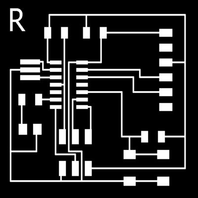
I then worked on exporting the outline of the circuit board,using wire tool.I exported the board outline using the exact same settings as before – monochrome, 500 dpi, window. Make sure the window size is exactly the same (e.g. 824x740). If you resize the window between the circuit export and the outline export, the exported pngs will be different size files (pixels wide by pixels tall) and not lined up together (different origins).

Then I used photoshop to invert the colors.Otherwise, Fab Modules will cut on both the inside and the outside of the line.

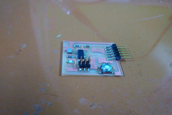
Milling
Using the Modela MDX-15 with Fab Modules, I first cut the traces with a 1/64" endmill and the cut out the board outline using a 1/32" endmill.

Then after picked up the components I soldered the board.It was bit tricky since the paths were tiny.So next I make boards I need thick paths.Here is the final board:
Download files: